Design and processing of main mold components
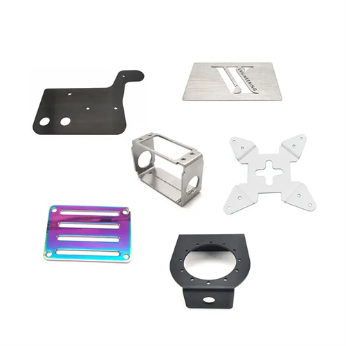
Key mold components include the punch, die, mold base, guides, and positioning devices. Their design and processing quality directly determine the mold’s precision, lifespan, and part quality. Design requires selecting the appropriate material and structure based on the mold’s operating conditions (such as forming material, forming force, and production batch). Processing requires high-precision equipment and processes to ensure that the component’s dimensional accuracy, shape precision, and surface quality meet design requirements.
As the core working components of a mold, the punch and die require key design considerations for strength, wear resistance, and forming accuracy. Punches come in various structural styles: integral, modular, and inlay. Integral types are suitable for simple shapes and small-batch production, while modular and inlay types are suitable for complex shapes and large-scale production, facilitating machining and replacement. Materials typically used are alloy tool steels such as Cr12 and Cr12MoV, achieving a hardness of 58-62 HRC after quenching to enhance wear resistance. The machining process includes roughing (forging, annealing), semi-finishing (milling, grinding), finishing (wire cutting, EDM), and fine grinding after heat treatment, ensuring that the working portion of the punch achieves IT6-IT7 dimensional accuracy and a surface roughness Ra ≤ 0.8μm. For example, the punch for automotive panel stamping dies is made of Cr12MoV. After forging, it is milled to shape, the cutting edge is machined by wire cutting, and finally fine-ground to ensure a cutting edge straightness error of ≤ 0.01mm/100mm.
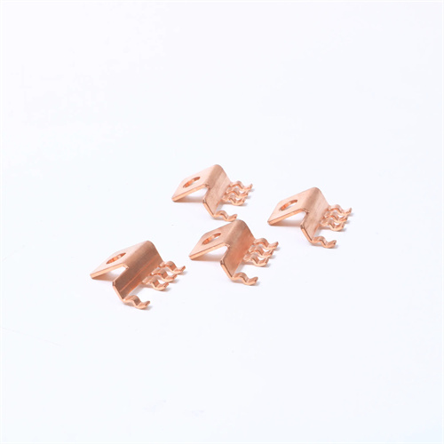
The die base consists of an upper die base, lower die base, guide pins, and guide bushings. The design must ensure sufficient rigidity and guiding accuracy. The upper and lower die bases are typically constructed of HT300 gray cast iron or Q235 steel plate. Thickness varies depending on die size and forming force, typically ranging from 50 to 200 mm. The guide pins and bushings are constructed of 20Cr or GCr15 bearing steel. After carburizing and quenching, the guide pins achieve a hardness of 58-62 HRC, while the guide bushings achieve an inner hardness of 55-60 HRC. The fit accuracy is H7/h6, ensuring a guide clearance of ≤0.01 mm. During machining, the die base surface must be ground to a parallelism error of ≤0.02 mm/100 mm. The outer and inner diameters of the guide pins and bushings are ground to an IT5 level of precision, with a surface roughness of Ra ≤0.4 μm. For example, the mold frame of small and medium-sized molds has a guide column diameter of 20mm and a guide sleeve length of 50mm. The outer circle and inner hole are ground by a centerless grinder to ensure that the roundness error is ≤0.005mm. After assembly, the sliding resistance of the upper mold base along the guide column is uniform and there is no sticking phenomenon.
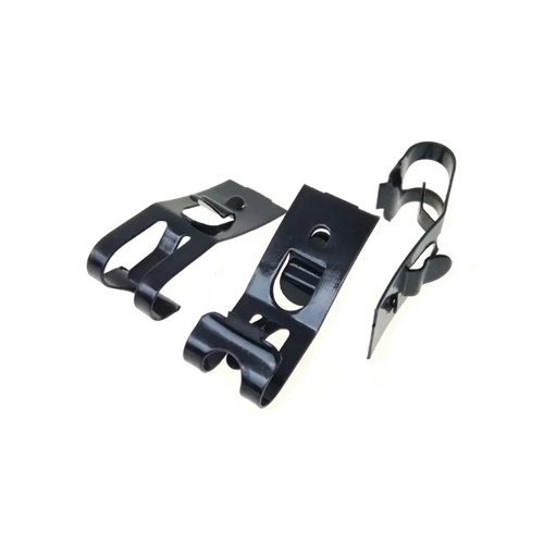
The design of positioning devices (such as locating pins, baffles, and side cutting edges) must ensure the positioning accuracy of the blank, with a positioning error of ≤0.05mm. The locating pins are made of 45 steel or Cr12, with a hardness of 50-55HRC after quenching, and the heads are rounded or chamfered to avoid scratching the blank. The positioning surface of the baffle plate must be flat, and the edge in contact with the blank must be blunt, with a surface roughness of Ra ≤1.6μm. During processing, the external cylindrical grinding accuracy of the locating pins reaches IT6 level, and the positioning surface of the baffle plate is milled and then ground to ensure a flatness error of ≤0.01mm. For example, the side cutting edges in progressive dies are made of Cr12 material and formed by wire cutting. The edge roughness is Ra ≤0.8μm, ensuring that the step error of each feed is ≤0.03mm.
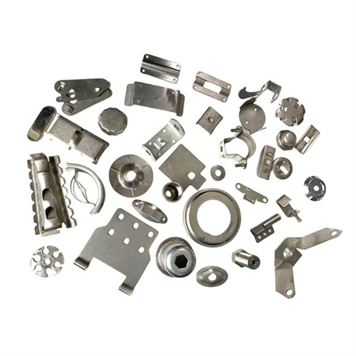
The machining process for mold components must be tailored to the material and precision requirements. For high-hardness materials (such as quenched tool steel), specialized machining methods such as EDM and wire cutting are required. For low-hardness materials (such as cast iron and steel plates), conventional machining methods such as milling and grinding can be used. During machining, appropriate heat treatment steps must be implemented, such as annealing after forging to eliminate internal stresses, tempering after rough machining to improve material toughness, and quenching before finishing to increase hardness. For example, the machining process for a die: forging → annealing → milling → drilling → rough grinding → quenching → fine grinding → wire cutting → polishing. Each step requires inspection to ensure quality. With the advancement of machining technology, the application of advanced machining methods such as high-speed milling and wire cutting can improve the machining precision of mold components by one or two grades, increasing production efficiency by over 30%.