Application of wedge and slide in multi-position progressive die
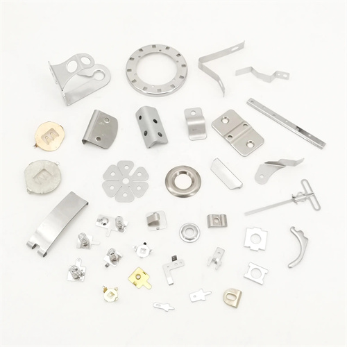
In multi-station progressive dies, cams and sliders are core components for complex forming processes, particularly suited for the production of precision parts requiring simultaneous multi-directional machining. Multi-station progressive dies utilize continuous material feeding to complete multiple processes, including blanking, bending, and drawing. The combination of cams and sliders transcends the limitations of traditional vertical motion, enabling horizontal, inclined, and even complex forming operations, significantly improving production efficiency and part precision. In the mass production of small, complex parts such as electronic connectors and automotive components, the use of cams and sliders can increase process integration by over 40%, reducing mold footprint and equipment investment.
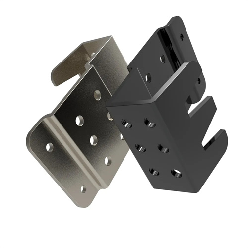
In the side stamping station, the combination of a wedge and a slider allows for punching holes perpendicular to the material feed direction, solving the problem of side hole processing that is difficult to accomplish with traditional progressive dies. For example, the side locating holes (0.8mm diameter) of mobile phone connectors must be completed synchronously in the progressive die. A 15° wedge is used to drive the slider, with a micro punch mounted on its end. As the material is fed, the wedge moves downward with the upper die, pushing the slider laterally. After the punch completes the side hole punching, a spring return mechanism drives the slider back to its original position. The entire process is precisely synchronized with the material feed rhythm. To ensure stamping accuracy, the slider is guided by a precision ball guide with a clearance of 0.005-0.01mm. The coaxiality error between the punch and the die is ≤0.01mm, ensuring hole tolerances within ±0.02mm.
An inclined wedge and slider enable complex angle forming in the bending process of a multi-station progressive die, particularly asymmetric bends such as Z- and U-shapes. In a progressive die for a certain automotive seatbelt buckle, a 90° lateral bend is required at the fifth station. A 30° inclined wedge drives the slider, which is mounted on a bending punch, while the die is fixed below the station. When the material reaches this station, the inclined wedge pushes the slider forward, and the punch and die cooperate to complete the bend. A holding device simultaneously prevents material slippage. Due to the continuous feeding characteristics of the progressive die, the slider stroke must strictly match the material pitch (25mm). Calculation determined the inclined wedge stroke to be 14.4mm (25/sin30°), and mechanical limit blocks were set to control the slider’s end position. This allows the bending angle error to be controlled within ±0.5°.
In a combined drawing and shaping station, the combination of a cam and slider applies radial pressure, addressing wrinkling during the deep drawing of thin-walled parts. In the progressive die drawing station for a micromotor housing (10 mm diameter, 8 mm height), a 45° cam is used to drive three sets of circumferentially evenly spaced sliders, with shaping bumps mounted on the inside of the sliders. During the drawing process, the cam drives the sliders toward the center, applying uniform radial pressure to the workpiece’s outer diameter, suppressing wrinkling and improving the workpiece’s roundness (≤ 0.03 mm). The synchronicity of the sliders is ensured by the isometry of the cam’s slope, and the motion error of each slider is controlled within 0.01 mm, preventing ovalization or localized deformation of the workpiece.
The layout of the cams and sliders in multi-station progressive dies must adhere to the principle of process integration, concentrating stations with similar functions to reduce the number of cam types and slider specifications. For example, a connector progressive die contains eight stations, with the lateral stamping and lateral bending stations arranged adjacent to each other. They share a cam drive system, which uses a cam switching mechanism to switch slider functions, reducing mold complexity. Furthermore, interference between the slider and the feed mechanism must be considered. The slider’s return position must be at least 0.5 mm above the material surface, and the cams must be installed away from the feed channel to ensure collision-free operation during high-speed stamping at 300 strokes per minute.
Regarding maintenance and debugging, the cams and sliders in multi-station progressive dies require easily adjustable clearance compensation mechanisms. For example, grindable adjustment shims are installed on the slider guide rails. After every 100,000 pieces, the shims are ground to compensate for wear (typically 0.01-0.02mm). The lubrication system utilizes a centralized oil supply system, regularly injecting high-temperature grease into the cam bevel and slider guide rails (every eight hours) to reduce the coefficient of friction (to within 0.08). These measures ensure that the service life of the cams and sliders exceeds 500,000 cycles, meeting the demands of high-volume production.