Determination of bending plan for workpiece
Determining the bending plan is the primary step in bending process design, directly impacting part quality, production efficiency, and mold costs. The bending plan must be developed based on factors such as part shape, dimensional accuracy, material properties, and production batch size. It includes planning the bending process, selecting the bending direction, determining the bending equipment, and designing the mold structure. A reasonable bending plan ensures that defects such as cracking and wrinkling are avoided during the bending process, while also simplifying the mold structure and improving production efficiency.
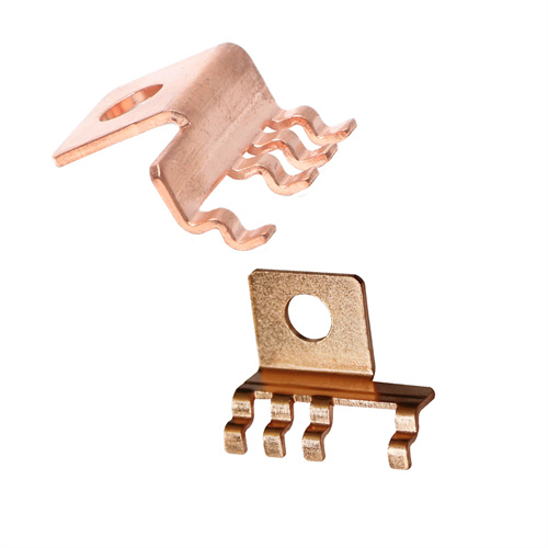
Bending processes should be arranged according to the principle of “from simple to complex, starting with the easy and then moving on to the difficult.” Simple bends (such as V- and U-shaped parts) can be bent in a single process. Complex bends (such as multi-angle bends and irregular shapes) require multiple steps to avoid excessive material deformation or mold interference caused by a single bend. For example, bending a Z-shaped part can be divided into two steps: first bending to an acute angle, then bending to an obtuse angle. Bending in a single step can easily lead to uneven deformation in the middle. For bent parts with holes, the order of bending and punching should be determined based on the hole’s location. If the hole is outside the bending deformation zone, punching can be performed before bending. If the hole is within the bending deformation zone, bending should be performed before punching to avoid deformation during bending. For example, if the hole on the side of a U-shaped part is more than 5mm from the bend line, punching can be performed before bending. If the distance is less than 5mm, bending should be performed before punching.
The choice of bending direction must consider the material’s rolling direction and the intended use of the part. The material exhibits better plasticity along the rolling direction and is less prone to cracking when bent. Therefore, the bending direction should be perpendicular to the rolling direction whenever possible. For example, the rolling direction of low-carbon steel plates is parallel to their length. When bending the long side, the bend line should be perpendicular to the length, that is, perpendicular to the rolling direction, to reduce the risk of cracking. For parts with specific appearance requirements, the bending direction must avoid scratches or defects on the material surface to ensure acceptable appearance. Furthermore, the bending direction must be coordinated with the die’s feed direction. For progressive die bending, the bending direction should facilitate continuous feeding to reduce positioning errors between process steps.
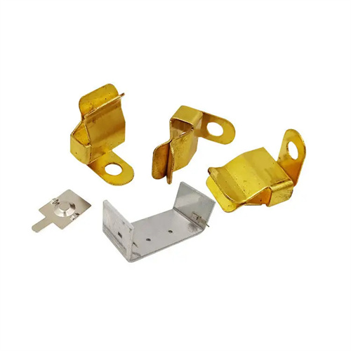
The selection of bending equipment depends on the bending force, part size, and production batch size. Common bending equipment includes conventional presses, press brakes, and specialized bending machines. Conventional presses are suitable for mass production of small and medium-sized parts and, when combined with specialized bending dies, achieve high-precision bending. Press brakes are suitable for bending large sheets, offering high flexibility and adaptability to small batches and a wide variety of products. Specialized bending machines are ideal for the efficient production of parts with specific shapes, such as tubular parts. For example, for mass production of U-shaped parts with a thickness of 3mm and a width of 200mm, a 100kN conventional press combined with a U-bending die is suitable. For bending large steel plates with a length of 2000mm, a press brake is more suitable. The equipment’s stroke and work surface dimensions must meet the requirements for both die installation and part forming. The stroke should be greater than two to three times the part height, and the work surface should be larger than the die installation dimensions.
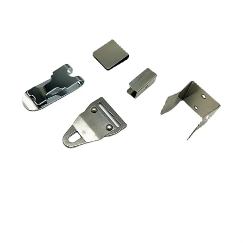
Die design is the core of a bending solution. The appropriate die type, such as single-step, progressive, or compound, must be selected based on the bending process and part shape. Single-step dies are simple and suitable for small-batch production of simple parts. Progressive dies can perform multiple bending steps within a single die set, making them suitable for large-scale production of complex parts. Compound dies can complete bending and other steps (such as punching and cutting) in a single stroke, improving production efficiency. For example, multi-angle bending of electronic connectors utilizes a progressive bending die with five bending stations and a production rate of 30 parts per minute. Small-batch production of simple L-shaped parts utilizes a single-step bending die to reduce die costs. The die’s positioning mechanism must ensure bending accuracy, with a positioning error of ≤0.05mm. Guides (such as guide pins and sleeves) must ensure proper alignment of the male and female dies, with a clearance error of ≤0.02mm.
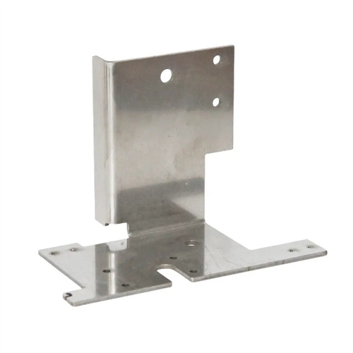
Bending plans must be verified through die trials. During these trials, the dimensional accuracy, surface quality, and deformation of the part are checked, and the plan is adjusted based on the results. If cracking occurs, the bending radius should be increased or the rolling direction adjusted. If springback exceeds tolerance, the punch angle should be modified (allowing for springback compensation) or a correction step should be added. If dimensional accuracy is insufficient, the die positioning mechanism should be optimized. For example, a stainless steel U-shaped part exhibited 5° springback after die trials. The punch angle was adjusted from 90° to 85°, and the angle passed after another die trial. A bent part with a hole exhibited hole deformation after die trials. Adjusting the punching process to perform the hole after bending resolved the hole deformation issue. Through die trials and solution optimization, the final bending plan must meet all technical requirements of the part while also balancing production efficiency and cost.