Calculation of unfolded dimensions of workpiece
Calculating the unfolded dimensions of a part is a crucial step in stamping process design. This involves restoring the dimensions of the original blank after bending, drawing, or other forming processes. Its accuracy directly impacts the part’s dimensional precision and material utilization. The fundamental principle of unfolded dimension calculation is the conservation of volume (which can be simplified to the conservation of area when ignoring material thickness variations), meaning that the volume (or area) of the formed part is equal to that of the blank. Calculating unfolded dimensions varies depending on the forming process (such as bending or drawing), and the appropriate formula must be selected based on the part’s shape and deformation characteristics.
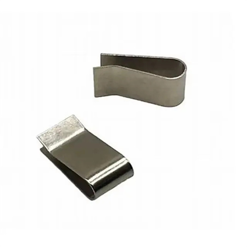
The calculation of the unfolded dimensions of a bent part requires consideration of the effects of the bend radius and material thickness on the position of the neutral layer. The neutral layer is the fiber layer that neither expands nor contracts during bending and its length is equal to the unfolded length of the blank. The position of the neutral layer is represented by the radius of curvature ρ, where ρ = r + kt, where r is the inner radius of the bend, t is the material thickness, and k is the neutral layer displacement coefficient (0.3-0.5). When r/t > 5, k = 0.5 (the neutral layer is located in the middle of the material thickness). When r/t ≤ 5, k decreases as r/t decreases. This value can be determined using a table or empirical formula. For example, if r = 2 mm, t = 1 mm (r/t = 2), and k = 0.35, then ρ = 2 + 0.35 × 1 = 2.35 mm. The unfolded length, L, of a bent part is equal to the sum of the straight segment length and the neutral layer length of the bent section: L = l1 + l2 + πρθ/180° (l1 and l2 are the straight segment lengths, and θ is the bend angle ). For example, for a 90° bend, l1 = 30 mm, l2 = 40 mm, and ρ = 2.35 mm. The unfolded length, L, is 30 + 40 + 3.14 × 2.35 × 90/180 ≈ 70 + 3.14 × 2.35 × 0.5 ≈ 70 + 3.68 ≈ 73.68 mm.
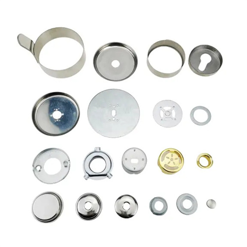
The calculation of the unfolded dimensions of drawn parts is based on the principle of conservation of area. For flangeless cylindrical parts, the blank diameter D is calculated as: D = √(d² + 4dh), where d is the part diameter and h is the part height. When the material thickness t is large (t>3mm), the effect of thickness on the dimensions must be considered. The formula is modified to: D = √[(d + t)² + 4 (d + t)(h – 0.43t)]. For example, for a cylindrical part with a diameter of 50mm, a height of 100mm, and a thickness of 2mm, D = √(50² + 4×50×100) = √(2500+20000) = √22500 = 150mm. Taking the thickness into account, D = √[(50+2)² + 4×(50+2)×(100-0.86)] ≈ √[2704 + 4×52×99.14] ≈ √[2704+20626] ≈ √23330 ≈ 152.7mm. For cylindrical parts with flanges, the blank diameter D = √(d² + 4dh + 4d 凸²) (d 凸 is the flange diameter). Ensure sufficient material in the flange area.
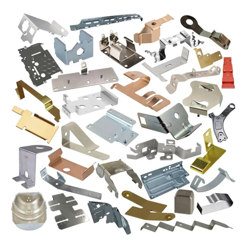
The unfolded dimensions of complex-shaped parts require a segmented approach. This involves breaking the part down into simple geometric units (such as straight lines, arcs, and cylinders), calculating the unfolded dimensions of each unit separately, and then summing the total. For example, a U-shaped part with a boss can be broken down into a straight bottom segment, two curved sections, and the boss portion. The unfolded lengths of each section are calculated separately and then added together. For extremely complex parts, the unfolded dimensions can be determined experimentally. A small-scale prototype is first produced for trial punching, and the blank dimensions are adjusted based on the test results until the part meets acceptable dimensions. For example, the unfolded dimensions of automotive panels are typically determined through trial punching of a 1:1 prototype, then optimized through CAE simulation analysis to ensure material utilization and part accuracy.
Correction of unfolded dimensions must account for factors such as material thinning, springback, and mold clearance during the forming process. For bent parts, springback can cause deviations between the actual and theoretical dimensions, necessitating a correction factor (typically 0.1%-0.3%) in the unfolded dimensions. For example, a 0.2% correction factor should be added to the calculated unfolded length of a high-precision bent part to compensate for the shortening caused by springback. For drawn parts, material thinning can increase the actual height, necessitating an appropriate reduction in unfolded dimensions (approximately 0.5%-1%) to prevent height deviations. Furthermore, uneven mold clearance can lead to uneven material flow, necessitating adjustments to the unfolded dimensions based on the results of die trials. For example, if a drawn part’s height after die trials exceeds the design by 2mm, the blank diameter needs to be reduced by 1mm to meet the required height.
Calculated unfolded dimensions must be verified through a trial mold. During trial molds, a prototype is produced using the calculated blank dimensions. After forming, key dimensions of the part are measured and compared to the designed values, and the unfolded dimensions are adjusted. If the part dimensions are smaller than the designed values, the blank is undersized and the unfolded dimensions need to be increased; if they are larger than the designed values, the unfolded dimensions need to be reduced. For example, if a bent part has a designed length of 100mm and the actual length after trial molds is 98mm, the unfolded length needs to be increased from the calculated 99mm to 101mm. Alternatively, if a drawn part has a designed diameter of 50mm and the actual diameter after trial molds is 51mm, the blank diameter needs to be reduced from 150mm to 148mm. For mass-produced parts, the unfolded dimensions determined during trial molds must be incorporated into the process documentation as a basis for blank blanking to ensure production stability. With the advancement of computer technology, CAE simulation software (such as Dynaform and AutoForm) can accurately calculate the unfolded dimensions of complex parts. By simulating material flow, they can predict the final dimensions after forming, reducing the number of trial molds and improving computational efficiency.