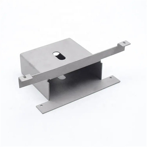
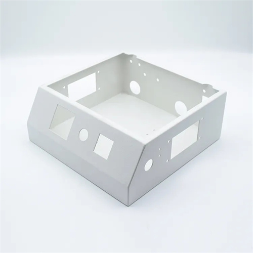
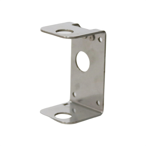
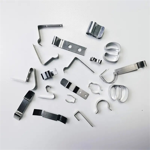
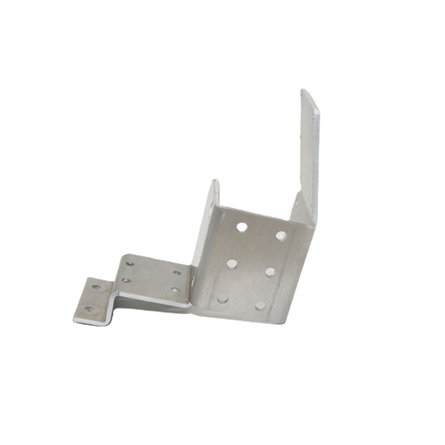
Bending die assembly
Bending die assembly involves combining qualified mold parts into a complete mold according to design requirements. This process directly impacts the mold’s precision, lifespan, and the quality of the bent part. The assembly process must ensure the relative positioning accuracy, clearances, and movement flexibility of each component. Following the principles of “benchmark first, then general, inside first, then outside, bottom first, then top,” a reasonable assembly sequence and adjustment methods are employed to ensure the mold meets operational requirements. The key components of a bending die assembly include the punch, die, positioning device, press, ejector, guide, and die frame, and the assembly quality of each component must be strictly controlled.
Pre-assembly preparation is fundamental to ensuring assembly quality. All parts must be cleaned and inspected to remove burrs and oil stains. The dimensional accuracy, form accuracy, and surface roughness of the parts must be checked to ensure they meet design requirements. Special attention should be paid to inspecting the working dimensions of the punch and die (such as corner radii, angles, and clearances), the parallelism and perpendicularity of the die frame (tolerance ≤ 0.02mm/100mm), and the fit accuracy of the guides (guide pins and guide bushings) (typically H7/h6). For example, the punch angle of a V-bending die must be checked to ensure it is 90° ± 0.05°, the die opening width must meet the design value, and the positioning error of the locating pins must be ≤ 0.03mm. Unqualified parts must be repaired or replaced to avoid compromising subsequent assembly accuracy.
The die frame is the first step in assembling a bending die. The die frame must be assembled with the upper and lower die bases, guide pins, and guide sleeves. The coaxiality error between the guide pins and sleeves must be ≤0.01mm, ensuring that the upper die base can move freely and smoothly along the guide pins. During assembly, the guide sleeves are first pressed into the upper die base, and the guide pins into the lower die base. Specialized tools (such as press sleeves) are used during the press-fit process to ensure vertical alignment and prevent deformation of the guide pins and sleeves. After press-fitting, the mating surfaces of the guide pins and sleeves are ground to ensure uniform clearance and smooth sliding. For example, using a 20mm diameter guide pin and sleeve (fitting H7/H6), the verticality of the guide pins is checked with a dial indicator after press-fitting, with an error within 0.01mm/m. The upper die base’s resistance to movement is manually tested to ensure uniformity and no sudden changes.
The assembly of the working parts is the core of bending die assembly. The punch is typically secured to the upper die base via a punch retaining plate, while the die is secured to the lower die base via bolts and dowel pins. During assembly, alignment and uniformity of the punch and die gaps must be ensured. For V-shaped bending dies, the gap between the punch and die is maintained by adjusting the punch’s position within the retaining plate. A feeler gauge is used to check for consistent clearances (to an error of ≤ 0.02mm). For U-shaped bending dies, parallelism and symmetry of the two walls must be ensured. The die is precisely positioned using dowel pins, and the punch height is adjusted using shims to ensure uniform clearances. For example, when assembling a U-shaped bending die, the die is first pre-secured with bolts. A dial indicator is used to calibrate the perpendicularity and parallelism of the die walls. Dowel pins are then inserted to secure the die. Finally, the punch is installed, and the gap between the punch and die is adjusted to 1.05t (where t is the material thickness). A feeler gauge is used to check for consistent clearances at all points.
The assembly of auxiliary devices includes the installation of positioning devices, pressure devices, and ejector devices. Positioning devices (such as positioning pins and retaining plates) must ensure positioning accuracy (error ≤ 0.05mm), and the surface in contact with the blank must be smooth and free of burrs. Pressure devices (such as pressure plates and springs) must ensure uniform pressure, with the pressure plate and die parallelism error ≤ 0.03mm. Ejector devices (such as ejector rods, springs, and cylinders) must ensure sufficient ejector force and flexible movement, with the ejector plate and die top surface parallelism error ≤ 0.02mm. For example, when assembling a U-shaped bending die with a spring ejector device, the spring compression must be adjusted to ensure the ejector force reaches the designed value (10% of the bending force). The ejector plate must then be tested for smooth lifting and ejection height.
Post-assembly commissioning is a critical step in verifying assembly quality. Trial molds are performed on the press to check the dimensional accuracy, surface quality, and working condition of the bent part. During trial molds, the punch and die are inspected for smooth fit, interference, or unusual noise. The angles and dimensions of the bent part are checked to ensure they meet requirements, and to ensure there is no cracking, wrinkling, or excessive springback. For example, when trialing a V-shaped bend, if the bend angle is too large (3° springback), the punch angle needs to be adjusted (reduced by 3°). If the angles are inconsistent, the alignment of the punch and die needs to be adjusted. Repeated adjustments and corrections are performed until the mold can consistently produce qualified parts. Finally, the mold undergoes an overall inspection, is oiled, and rust-proofed, and assembly is complete.