Key points of processing and assembly of progressive dies
The machining and assembly of progressive dies are critical to ensuring die precision and performance. Machining accuracy directly impacts part quality, while assembly quality determines die life and production efficiency. Progressive dies are complex structures with numerous parts, requiring high-precision equipment and advanced processes for machining. Assembly adheres to strict procedures and specifications to ensure coordinated operation of all parts and achieve continuous and stable stamping production.
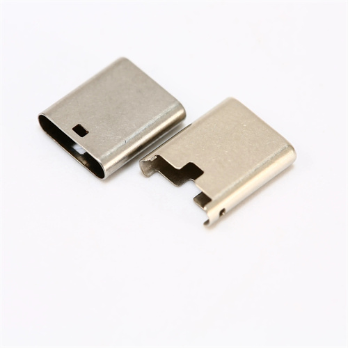
The key to machining progressive die parts lies in ensuring dimensional accuracy, form and position tolerances, and surface quality, with the machining of the working parts (punch and die) being a key focus. Punch machining typically utilizes processes such as grinding, wire cutting, and electro-spark forming. For circular punches, cylindrical grinding requires dimensional accuracy of IT6 and a roundness tolerance of ≤0.002mm. For special-shaped punches, wire cutting achieves a contour accuracy of ±0.005mm and a surface roughness of Ra 1.6μm or less. Bench grinding is performed as necessary to remove burrs from the cutting edges. The machining of dies requires ensuring the positional accuracy and uniformity of the die holes. Integral dies utilize jig grinding or electro-spark forming, achieving a hole position tolerance of ±0.005mm and a hole spacing tolerance of ≤0.003mm. The mating surfaces of segmented dies are surface-ground to a flatness of ≤0.002mm and a gap of ≤0.003mm. After being secured with pins and screws, the entire die is ground to ensure alignment of the die holes in each segment. The processing of guide parts such as guide pins and guide sleeves must ensure cylindricity and coaxiality. The cylindricity error after grinding is ≤0.001mm, and the fitting clearance between guide pins and guide sleeves is H7/h6, which meets the requirements of high-precision guidance.
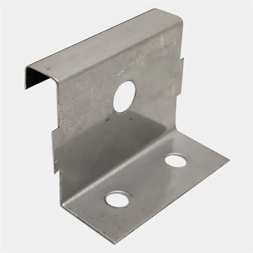
During the machining of template components (upper die base, lower die base, retaining plate, and backing plate), attention must be paid to flatness and parallelism. Large surface grinders are used for grinding, with flatness tolerances ≤ 0.02mm/m, parallelism ≤ 0.01mm/m, and a surface roughness Ra of less than 0.8μm. Holes in the template are machined using a machining center or jig boring machine. Positional tolerances for locating holes are ±0.005mm, and perpendicularity tolerances are ≤0.005mm/100mm, ensuring accurate positioning after part assembly. For large progressive dies (length > 2000mm), templates require aging treatment to eliminate internal stresses and prevent post-processing deformation. Aging treatment is performed at 200-250°C for 6-8 hours, followed by cooling before finishing. Template edges and openings require rounding (R0.5-R1mm) to avoid sharp angles and burrs, enhancing assembly safety.
The assembly of progressive dies must adhere to the principles of “benchmark first, general, internal first, external, and precision first, general.” Before assembly, all parts must be cleaned and inspected to remove oil, burrs, and check that the dimensions and form and position tolerances meet the drawing requirements. First, assemble the die base. Press the guide pins into the lower die base, and the guide sleeves into the upper die base. Use a press to press slowly to avoid tilting. Ensure uniform clearance between the guide pins and sleeves. Use a dial indicator to check the verticality of the guide pins, with an error of ≤0.01mm/100mm. Then, assemble the retaining plate and backing plate. Position them using locating pins and tighten with screws, ensuring parallelism between the retaining plate and the die base of ≤0.01mm/m. The assembly of the working parts is crucial. When the punch is pressed into the retaining plate, it must be supported with equal-height blocks to ensure verticality. The die is mounted on the backing plate, and shims are adjusted to ensure parallelism between the die and the retaining plate. The gap between the punch and die must be uniform, and a feeler gauge should be used to check the clearance at all locations, with a deviation of ≤0.01mm.
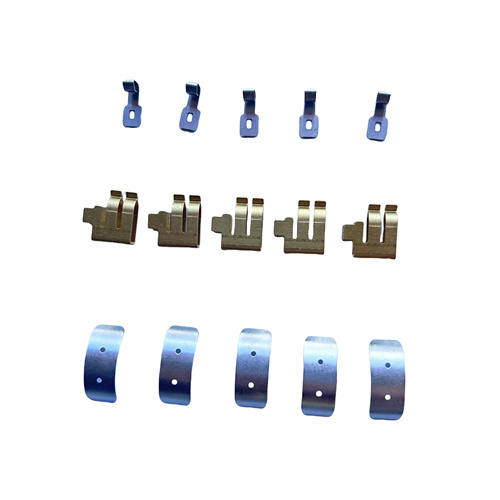
The assembly of the positioning and feeding system must ensure accurate positioning and smooth feeding. The side blades and stop pins are installed on the die or stripper plate with a positioning tolerance of ±0.01mm and a clearance of 0.1-0.3mm with the edge of the strip. The guide pins are installed on the punch fixing plate, with the height of the head protruding from the stripper plate 1-1.5 times the material thickness to ensure reliable guidance. The feed mechanism (such as feed rollers and clamps) must be coaxial with the mold to an error of ≤0.02mm, and the feed direction must be parallel to the mold centerline to ≤0.01mm/m to avoid lateral forces when feeding the strip. The assembly of the stripper device must ensure the stripper plate moves flexibly, with a clearance of 0.05-0.1mm with the punch, uniform spring or rubber force, and the stripper force meets the design requirements. The stripper force at each point should be tested with a dynamometer, with a deviation of ≤10%.
The trial and adjustment of a progressive die is the final step in verifying machining and assembly quality. Before trial, the mold must be checked for correct assembly, the flexibility of all moving parts, and the reliability of safety devices. During trial, the same materials and process parameters as in production are used, and the stamping speed is gradually increased. The smooth feeding of the strip material, the conformity of the part, and the presence of defects such as burrs, wrinkles, and cracks are observed. If stepover error is found to be excessive, the position of the guide pins or the feeding parameters must be adjusted. Uneven clearance between the punch and die requires correction by grinding the die or adjusting the punch position. If material removal is difficult, the spring must be replaced or the stripper plate clearance adjusted. After successful trial, a small production run (500-1000 pieces) is conducted to further verify mold stability. Mold operating parameters and part quality data are recorded, and a trial report is compiled to provide guidance for subsequent mass production. Through strict control of the machining and assembly processes, the service life of a progressive die can reach over one million cycles, ensuring efficient and stable production.