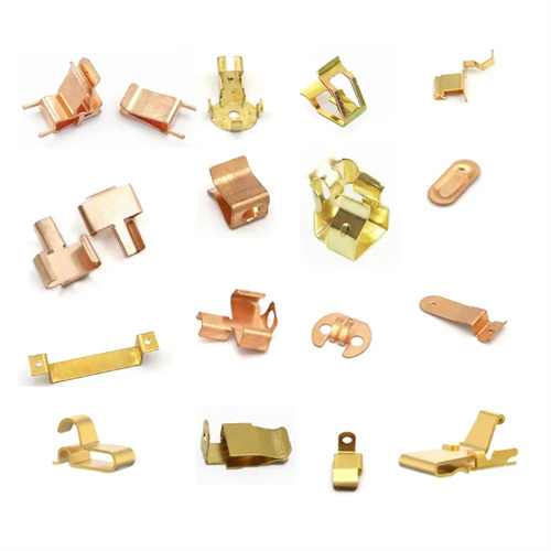
Design of sealing, blanking and deep drawing compound die
The design of a combined blanking and drawing die for sealing plugs is an integrated forming technology developed for small plugs used for sealing in pipeline systems. These parts are typically cup-shaped (10-30mm in diameter, 8-25mm in height) and are primarily made of mild steel (such as Q235) or brass (H62). After forming, they require uniform wall thickness, burr-free edges, and a sealing surface flatness tolerance of less than 0.05mm. The core advantage of this die lies in combining the blanking and drawing processes, reducing equipment usage and process flow. Production efficiency can reach 150-200 pieces per minute, making it suitable for high-volume production in areas such as automotive braking systems and hydraulic pipelines. Initially, the blank diameter must be calculated based on the final dimensions of the sealing plug. For a mild steel sealing plug with a diameter of 20mm and a height of 15mm, the blank diameter, calculated using a drawing factor of 0.65, is approximately 31mm. A 0.5mm trimming allowance should also be reserved to ensure a smooth edge after drawing.
The mold structure adopts an inverted layout and consists of a blanking die, a blanking punch (which also serves as a drawing die), a drawing punch, an elastic blank holder, and a discharge device. The blanking cutting edge is made of Cr12MoV steel, hardened to HRC58-62. The cutting edge clearance is set at 10% of the material thickness (0.02mm for 0.2mm thick material) to ensure smooth edges on the blanked part. The working surface of the drawing punch is polished to Ra0.2μm, with a corner radius of 8-10 times the material thickness (1.6-2mm for 0.2mm thick) to prevent cracking during drawing. The corner radius of the drawing die (blanking punch) is slightly larger, at 10-12 times the material thickness (2-2.4mm), to guide the material into the cavity smoothly. The blank holder is made of polyurethane rubber (hardness 80 Shore A) to provide blank holding force, and the force value is controlled at 3-5kN, which can prevent wrinkles and will not cause excessive thinning of the material due to excessive pressure (the thinning rate needs to be less than 10%).
The process coordination mechanism ensures the continuous execution of blanking and drawing, utilizing a spring-slider combination to control the timing of the movements: as the upper die descends, the blanking punch first engages the die to complete blanking, followed by the drawing punch synchronously contacting the blank to begin drawing. The gap between the two movements is less than 0.1mm, preventing material shifting. To meet the sealing requirements of the sealing plug, a small boss (0.3-0.5mm in height) is incorporated into the bottom of the drawing punch. During the drawing process, this bottom is locally thickened, resulting in a sealing surface thickness that is 15%-20% thicker than the barrel wall, enhancing sealing performance. An annular discharge groove (2mm wide, 1mm deep) is provided at the bottom of the die, which, combined with a compressed air blower, promptly removes blanking waste to prevent accumulation and die jamming.
The positioning and guiding system utilizes a dual guide post + lateral guide plate combination. The guide posts have a diameter of 16mm and a clearance of 0.005-0.01mm, ensuring a coaxiality error of less than 0.02mm between the punch and die. Blank positioning is achieved via stop pins and guide plates, with a pin position accuracy of ±0.1mm. The guide plate spacing is 0.1-0.2mm greater than the blank width, ensuring smooth feeding. Coil feeding is equipped with a servo feeder (step accuracy of ±0.03mm) and a leveling device to eliminate rolling stress and prevent distortion after deep drawing (perpendicularity error must be less than 0.1mm/m).
During commissioning and quality control, special attention should be paid to parameters related to sealing performance. During mold trials, 50 samples should be taken for wall thickness testing. The wall thickness deviation should be less than 0.1mm. The sealing surface flatness should be measured using a laser interferometer. Parts that exceed this tolerance should be repaired by grinding the sealing surface. After every 5,000 pieces are produced, the blanking edge wear should be inspected (allowable wear less than 0.03mm). If scratches appear on the drawing punch surface, polish it with diamond paste (grit size W5). During mold maintenance, the discharge chute should be cleaned weekly and the air pressure of the blower device should be checked (maintained between 0.4-0.6MPa) to ensure smooth waste discharge. High-temperature grease (resistant to temperatures exceeding 120°C) should also be applied to the guide pins and sleeves to extend their service life.