Design of progressive die for punching and bending of shielding cover
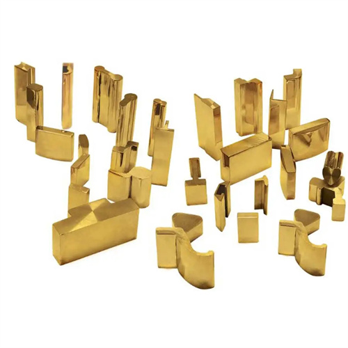
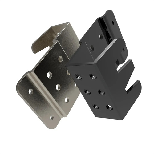
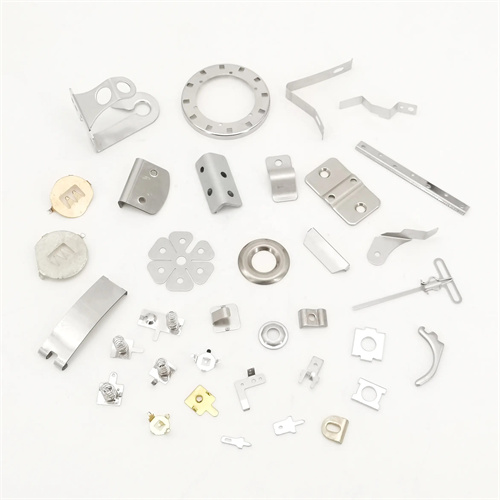
The design of a progressive die for punching and bending shield covers is a multi-station continuous forming technology developed for metal enclosures used for electromagnetic interference shielding in electronic devices. It can complete punching (mounting holes, heat dissipation holes) and multiple bending processes (90° hems, U-shaped grooves) within a single die. Production rates reach 100-200 parts per minute, with a dimensional accuracy of ±0.05mm. It is suitable for materials such as tinplate and brass strip with thicknesses of 0.1-0.5mm. Shield covers often have complex three-dimensional structures (such as boxes with multiple bends). The core of the progressive die lies in the strategic arrangement of 10-15 stations to achieve gradual material deformation and avoid interference between processes. CAD/CAE software is used to simulate the stress distribution at each station during the initial design phase to ensure that the maximum stress does not exceed 90% of the material’s yield strength (brass H62 ≤ 270MPa).
The mold structure adopts a horizontally arranged progressive layout. Typical workstations include: Station 1 punches pilot holes and pre-punches; Stations 2-4 punch heat dissipation holes (φ0.8-φ2mm); Stations 5-7 perform three 90° bends (with increasing bend height); Stations 8-10 form the U-shaped groove and side flanges; Station 11 performs shaping; and Station 12 performs blanking. Key components are carefully selected for their materials. The punching punch is constructed of W6Mo5Cr4V2 high-speed steel (HRC 62-65 hardness), with an EDM-hardened cutting edge for a lifespan of over 500,000 cycles. The bending die is constructed of Cr12MoV steel (HRC 58-62), with a surface polished to Ra 0.2μm to minimize scratches during bending.
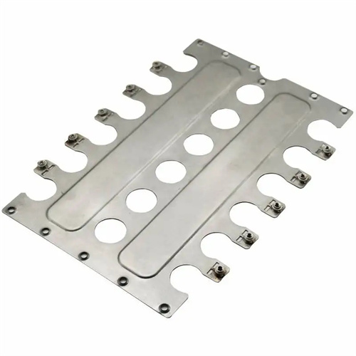
Coordinating punching and bending is a technical challenge. The principle of “punching first, bending later” is adopted to prevent deformation after bending from affecting hole positioning accuracy. The distance between the heat dissipation hole and the bend line must be ≥ twice the material thickness (≥ 1mm for 0.5mm thick material) to prevent cracking at the hole edge. The bending station is equipped with an elastic clamping device using polyurethane rubber (hardness 70 Shore A) to provide a clamping force (0.5-1kN) to ensure that the material does not slip during the bending process. The corner radius of the bending punch is 1-2 times the material thickness (0.5-1mm for 0.5mm thick), and a 0.5° springback compensation angle is set to ensure a bending angle accuracy of ±0.5°.
The feeding and positioning system utilizes high-precision servo control. After leveling, the coil is fed by a ball screw feeder with a step accuracy of ±0.01mm. A set of guide pins (φ2-φ3mm) are installed every two stations, which, in conjunction with guide holes (H7/g6), achieve secondary positioning, resulting in a cumulative positioning error of less than 0.03mm. For shield covers with flanges, a shaping station is installed before blanking. Upper and lower shaping blocks apply a pressure of 10-15MPa to the flanges to eliminate internal stress and ensure flange flatness of less than 0.05mm.
Commissioning and quality inspections focus on detail. During mold trials, an image measuring instrument is used to inspect the forming dimensions at each workstation, focusing on the distance between the hole position and the bend line (tolerance ±0.03mm). Any deviations are corrected by fine-tuning the punch position (±0.01mm). After every 10,000 pieces are produced, the punch is inspected for wear (replaced if diameter wear exceeds 0.01mm). The corner radius of the bending die is inspected with a profilometer and reground if wear exceeds 0.02mm. During mold maintenance, the waste channel is cleaned daily to prevent clogging by small punching waste (Ø0.8mm). The guide pins are inspected weekly and tightened if loose to ensure reliable positioning.