The quick-change die design is a high-efficiency die technology developed to meet the needs of high-variety, small-batch production. It is widely used in automotive parts, electronic components and other fields. It can quickly change the die within 5-15 minutes, significantly reducing equipment downtime. Compared with traditional die replacement, the efficiency is increased by more than 80%. Its core lies in the coordinated design of modular structure and quick locking mechanism. By standardizing the core components of the mold, such as the punch, die, positioning device, etc., and cooperating with the universal mold frame, rapid switching can be achieved. At the beginning of the design, the standardized interface dimensions of the modules need to be determined. For example, the diameters of the punch handle are standardized to three specifications: 25mm, 32mm, and 40mm, and the widths of the die positioning grooves are set to 10mm, 15mm, and 20mm to ensure that modules of different specifications are compatible with the universal mold base. For multi-variety production with stamping batches of 500-5000 pieces, quick-change dies can significantly reduce die change costs and increase equipment utilization to over 90%.
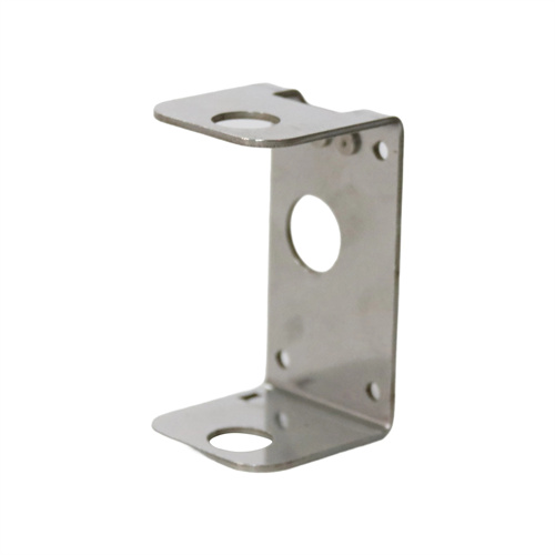
The mold structure consists of a universal die base, a quick-change punch assembly, a quick-change die set, a quick-change clamping mechanism, and a positioning datum. The universal die base is constructed of HT300 cast iron, 80-120mm thick, and is connected to the press table via T-slots. Standardized guide holes (20-30mm in diameter) and locating pin holes (10-16mm in diameter) are provided on the die base to ensure ±0.05mm repeatability of the quick-change module. The quick-change punch set consists of a punch, a punch holder, and a connecting shank. The punch is made of Cr12MoV, hardened to HRC 58-62. The punch holder is quenched and tempered from 45 steel and features a dovetail groove for quick engagement with the connecting shank, with a clearance of 0.01-0.03mm. The quick-change die set corresponds to the punch set. The die is secured to the die holder via an eccentric shaft locking mechanism with a locking force of 5-10kN, ensuring no loosening during the stamping process.
The core innovation of the quick-change die system is the rapid locking mechanism, which utilizes either an eccentric cam or hydraulic locking mechanism. The eccentric cam locking mechanism consists of a cam handle, a locking block, and a spring. Rotating the cam handle 180° locks and releases the die, with an operating force of less than 50N, making it suitable for small molds (weighing less than 50kg). The hydraulic locking mechanism, which uses a hydraulic cylinder to drive the locking pin, can achieve a locking force of 50-100kN and a response time of less than 1 second, making it suitable for large molds (weighing more than 100kg). Pressure sensors can also monitor the locking status in real time to prevent loosening. Both locking mechanisms ensure accurate positioning of the die, with a repeatability error of less than 0.03mm, to ensure consistent part dimensions after die changes.
The positioning and guiding system must balance speed and precision. Precision positioning keys (10-20mm width, H7 tolerance) are installed on the universal mold base and mate with the positioning slots (H6 tolerance) of the quick-change module to form a sliding guide with a clearance of 0.01-0.03mm. The punch and die are guided by ball guide pins and bushings with a diameter of 16-25mm. These pins are mounted on the quick-change module and replaced with the module, ensuring independent control of the guiding accuracy of each module. For demanding blanking parts (IT8 tolerance), a fine-tuning mechanism is required on the module. Bolts adjust the clearance between the punch and die (±0.02mm) to compensate for positioning errors.
Debugging and maintenance procedures need to be simplified. Each quick-change module must be pre-debugged before first use. The module number and corresponding part parameters (such as punch size and blanking force) must be recorded and stored in the mold management system. The parameters can be retrieved by scanning the code when changing molds. During routine maintenance, the locating keys and guide holes must be cleaned of iron filings and precision grease must be applied every 50 module changes. The locking force of the locking mechanism must be checked every 100 cycles, and the eccentric cam must be replaced if wear exceeds 0.1mm. Quick-change modules must be stored separately, using dedicated shelves and categorized by specification. Anti-rust oil must be applied to the working surface of the module to prevent loss of precision due to long-term storage.